Green AI & Software
Liquid Cooling for AI Data Centers: Solving the Massive Computing Power Strain
Artificial intelligence has pushed traditional digital infrastructure to a thermodynamic cliff. Discover how modern liquid cooling structures cut energy waste, slash Power Usage Effectiveness metrics, and future-proof high-density computing arrays.
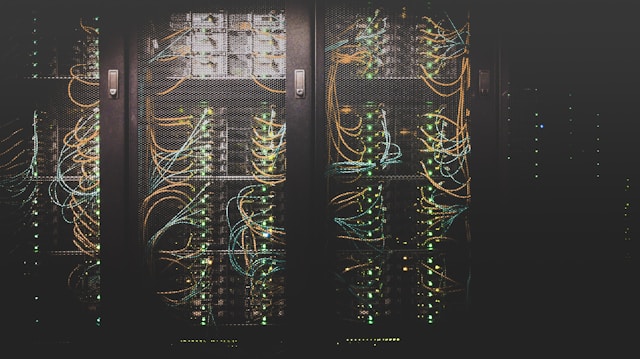
The global deployment of generative artificial intelligence has triggered an unprecedented digital infrastructure race. As hyperscalers and colocation providers rush to build AI-ready facilities, they are running into severe electrical and thermal limits. Traditional air-conditioned data center layouts are no longer capable of handling the extreme heat generated by modern hardware stacks.
The computing landscape has officially entered the era of ultra-high-density deployment. Next-generation processor architectures, such as the Nvidia Blackwell series, draw up to 1,200 watts per chip, pushing single-rack power requirements past 120 kW and moving toward 370 kW envelopes.
To prevent catastrophic thermal throttling and massive electrical waste, operators are overhauling their environmental management systems. Transitioning to advanced liquid cooling architectures represents the most effective path to maximize computing output while reducing the global carbon footprint of digital networks.
The Thermodynamic Cliff: Why Air Cooling Fails AI Workloads
Legacy data center infrastructure relies almost exclusively on air-chilling systems, utilizing heavy mechanical fans, air-handling units, and raised-floor tiles to circulate cold air through server chassis. This methodology was engineered for traditional cloud computing workloads, which rarely exceeded 10 kW to 15 kW per server rack.
Air is an exceptionally poor thermal conductor. When rack densities cross the 40 kW threshold, blowing ambient air across silicon boards can no longer dissipate heat fast enough to maintain safe operating temperatures.
Cooling Efficiency Comparison:
[Air Cooling Media] ──► Low thermal capacity, limits racks to 15 kW max.
[Liquid Cooling Media] ──► 3,500x more effective heat transfer, supports 100 kW+ racks.
This physical limitation introduces a severe energy penalty. Conventional air-cooled data centers must dedicate roughly 30 percent to 40 percent of their total electrical capacity solely to driving massive refrigeration compressors and high-powered fan arrays.
Furthermore, if a graphic processing unit (GPU) runs too hot, its internal safety software automatically lowers its processing speed to prevent structural meltdown. This thermal throttling directly degrades the system's power-to-compute performance, meaning expensive electricity is wasted without generating useful token outputs.
Core Liquid Cooling Architectures for High-Density Racks
To optimize liquid cooling data centers energy efficiency profiles, engineers deploy two primary decentralized cooling architectures that bring liquid media directly to the heat source.
1. Direct-to-Chip (Cold Plate) Cooling
Direct-to-chip systems utilize closed-loop pipe networks to pump a cooling liquid directly onto a sealed metal plate mounted flush against the processor. The underside of this cold plate features micro-channels that absorb heat from the silicon surface through conduction.
The liquid absorbs the thermal energy, travels away from the server chassis into an external heat exchanger, and returns chilled to repeat the process. This method allows data centers to retain their standard vertical server rack formats while removing up to 80 percent of the chip-level heat load without relying on air conditioning.
2. Immersion Cooling (Single-Phase and Two-Phase)
Immersion systems remove the concept of cold plates entirely by submerging full server blades into specialized, non-conductive dielectric fluids. Because every component, including the memory modules, power supplies, and logic boards, is fully surrounded by the liquid, the entire server achieves complete thermal uniformity.
Single-Phase Immersion: The dielectric fluid remains a liquid at all times, relying on automated pumps and external cooling distribution units (CDUs) to circulate the warmed liquid out to a dry cooler radiator.
Two-Phase Immersion: The dielectric fluid utilizes a low boiling point. As the chips heat up, the fluid boils and turns into a vapor, which rises to a cold condenser coil at the top of the sealed tank, releases its heat, condenses back into a liquid, and falls back into the bath.
Quantifying the Efficiency Gains: PUE and WUE Metrics
The primary tool used to measure the efficiency of a data center is Power Usage Effectiveness (PUE). The metric evaluates how much utility power enters the facility relative to the power consumed by the active computing hardware:
$$PUE = \frac{\text{Total Facility Energy Consumption}}{\text{IT Equipment Energy Consumption}}$$
An ideal data center would achieve a PUE score of 1.0, meaning every single watt of grid electricity goes directly to running the computational chips. While legacy air-cooled facilities regularly operate at inefficient PUE scores between 1.4 and 1.6, upgrading to a liquid-cooled setup slashes that ratio dramatically.
Infrastructure Cooling Performance Profiles
Operational Performance Metric | Legacy Air-Cooled Facilities | Direct-to-Chip Liquid Setups | Full Immersion Cooling Tanks |
Average Power Usage Effectiveness (PUE) | 1.45 to 1.60 | 1.12 to 1.18 | 1.03 to 1.06 |
Max Supported Rack Density | 15 kW to 20 kW | 100 kW to 150 kW | 200 kW to 300+ kW |
Internal Fan Power Consumption | High (10% to 15% of IT load) | Low (Minimal chassis fans) | Zero (Fans are removed entirely) |
Water Usage Effectiveness (WUE) | High (Evaporative loss risk) | Low (Closed-loop dry cooling) | Near Zero (Aqueous-free operation) |
Hardware Longevity Multiplier | Baseline standard | 1.2x lifespan extension | 1.5x lifespan extension |
Strategic Capital Integration: Waste Heat Recovery
Liquid cooling infrastructure introduces an exceptional secondary sustainability dividend: high-temperature warm water return loops. In an air-cooled facility, waste heat is exhausted into the sky as low-grade, diffused warm air that is virtually impossible to capture.
Liquid cooling systems return warm fluid from the racks at consistent temperatures ranging from 45°C to 65°C. This concentrated thermal energy can be directed straight into municipal district heating systems, agricultural greenhouses, or neighboring industrial manufacturing facilities.
By transforming a troublesome processing byproduct into a commercial heating asset, data center operators can meet strict localized environmental regulations while offsetting their total operational costs.
The Editorial Verdict
The rapid integration of artificial intelligence has turned power availability into the single greatest constraint facing global digital growth. Continuing to rely on legacy air-chilling methods to support next-generation hardware is an engineering impossibility.
Transitioning to high-efficiency liquid cooling solutions is a mandatory requirement to prevent regional power grids from buckling under the strain of advanced computation. By cutting cooling energy overhead by up to 90 percent, reducing water consumption, and enabling higher computing densities within small physical footprints, liquid cooling future-proofs data centers for the sustainable computing challenges ahead.
Related Articles
Climate Tech Innovations
Grid Enhancing Technologies: Multiplying Power Line Capacity Without New Cables

Climate Tech Innovations
Solid-State Hydrogen Storage: Eliminating High-Pressure Gas Risks

Climate Tech Innovations
Ocean Alkalinity Enhancement: Can We Safely Accelerate Marine Carbon Storage?
Climate Tech Innovations
Green Hydrogen Cost Per Kg 2026: The Clean Energy Pricing Reality

Climate Tech Innovations
Direct Air Capture: Can Tech Lower the Cost Per Ton of Carbon?

Climate Tech Innovations